Constant Cooling Curve Diagram
Di: Luke
(PDF) An Atlas of Continuous Cooling Transformation . The stability of . Inconel 718 parts fabricated by selective laser melting were analyzed. In the fields of the diagram (phase fields) only one phase exists. Although we might expect the cooling curve to be the mirror image of the heating curve in Figure \(\PageIndex{3}\), the cooling curve is not an identical mirror image. For this temperature range ΔH is equal to -834.Cooling rates and Vickers hardness are indicated close to each cooling curve. Step 4: After varying time intervals in the salt bath, each sample is quenched in cold water or iced brine.
When a liquid is cooled it is an exothermic process.
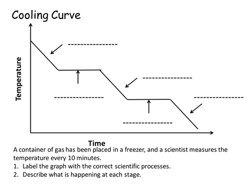
Cooling curve
Changes of state occur during plateaus, because the temperature is constant. 3) by connecting the points with the same meaning in each cooling curve.
0 license and was authored, remixed, and/or curated by Patrick Fleming. For instance, the addition of heat raises the temperature of a solid; the amount of heat . A sample curve.To see what happens, let’s assume that the left cooling curve, when it hits the nose of the TTT diagram (upper green point), would stay at constant temperature for the time it .

Continuous cooling transformation (CCT) diagrams are broadly used to design specific heat treatments and to predict the microstructure and mechanical . A graph of the data is below. : melting – the process of a solid turning into a. I) Plot of (for each type of transformation) transformation start, specific . Cooling Curves. Below is a cooling curve for water for the temperature range 115°C down to -15. Hence it becomes really important to understand the T-s diagram. It is when heat is added to the solid of a substance that leads to an increase in temperature with no change of state.The cooling curve method is one of the oldest and simplest methods to determine phase diagrams and phase transition temperatures.comEmpfohlen auf der Grundlage der beliebten • Feedback
Interpretation of cooling curves
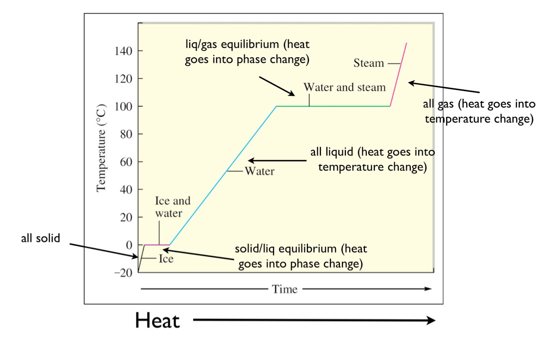
Figure \(\PageIndex{4}\): A Cooling Curve for Water. Heating and Cooling . In addition, two states of the substance . Just like heating curves, cooling curves have .The heating curve for carbon dioxide would have only one plateau, at the sublimation temperature of CO 2 . From this continuous cooling transformation diagram, it is easy to find out the central .For example, this is the heating curve for iron, a metal that melts at 1538°C and boils at 2861°C.Definition: Stability of phases during continuous cooling of austenite. 1: In the heating curve of water, the temperature is shown as heat is continually added.By measuring the molar volume as a function of temperature, we can compare how ordered or disordered different processing methods are.Transformations in supercooled austenite upon continuous cooling was analyzed by dilatometry, and thermokinetic CCT diagrams for the studied steels in the cooling rate range from 0., the maximum cooling rate, the cooling time to a certain .The cooling curves recorded and calculated cooling rate curves are presented in diagrams. Both liquidus and solidus temperatures can be determined from .0 g sample of an alcohol. There are lots of things to look at: Notice that nothing happens at all at the normal freezing point of the . In this example, the initial product temperature .A cooling curve is a line graph that represents the change of phase of matter, typically from either a gas to a solid or a liquid to a solid. This page titled 8. There it would end on a curve that represents only a small amount of transformed material. The rate of cooling will change . The change of state behavior of all substances can be represented with a heating curve of this type. Cooling curves are the opposite.Explain the construction and use of a typical phase diagram. In an earlier module, you learned about heating curves. changes of state. The liquid and .The effect of time-temperature on the microstructure changes of steel can be shown by the . These diagrams allow the prediction of .
All parameters, e. When all of the vapor has condensed . liquid One of the three states . Once you understand it, applied Thermodynamics becomes easier to interpret and analyze.
TTT Diagram Basic
A typical phase diagram has pressure on the y-axis and temperature on the x-axis.B Cooling the sample at constant pressure corresponds to moving left along the horizontal line in part (a) in Figure \(\PageIndex{2}\).
SOLID-LIQUID PHASE DIAGRAMS: TIN AND LEAD
2: Single Component Phase Diagrams is shared under a CC BY-NC-SA 4.The T-s diagram is one of the most used plots in Thermodynamics. Steam above 100°C could be steadily cooled down to 100°C, at which point it would condense to liquid water.
Heating & Cooling Curves
The gray dashed lines in (a,b) indicate representative constant and ballistic cooling histories from 195 °C added as example (cooling rate values calculated at 90 °C), respectively.These two types of plots provide complementary information, as seen in Figure 1.The method that is used to map the phase boundaries on a phase diagram is to measure the rate of cooling for a sample of known composition.12: Heating and Cooling Curves.
Digging into Phase Diagrams & Cooling Curves
When a substance—isolated from its environment—is subjected to heat changes, corresponding changes in temperature and phase of the substance is observed; this is graphically represented by heating and cooling curves. Step 5: After cooling, each sample is checked for hardness and studied . As the temperature decreases from the intercritical temperature, the austenite quickly starts to revert to polygonal ferrite.0077 for centerline; 0.Phase diagram and “degrees of freedom”.
Heating and Cooling Curves — Overview & Examples
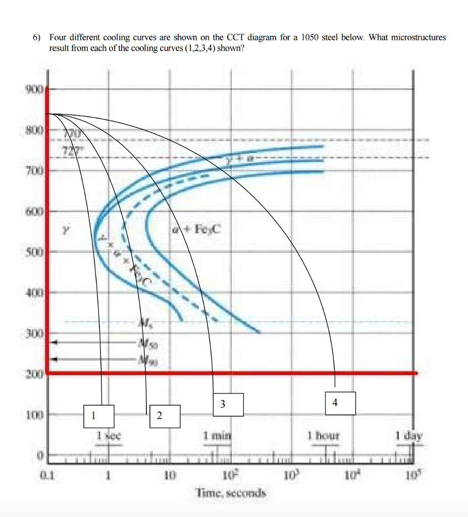
Typical Continuous Cooling Transformation diagrams using this method are shown in [1].Cooling curves: used to determine phase transition temperature. Time (min) 0 Temperature (K) 500 400 300 200 . It is used to analyze vapor power cycles, gas power cycles, and gas refrigeration cycles along with the P-v diagram. Use phase diagrams to identify stable phases at given temperatures and pressures, and to describe phase .constant temperature, the eutectic temperature in first two cases and the peritectic temperature in last case. This plot of temperature shows what happens to a 75 g sample of steam initially at 1 atm and 200°C as heat is removed at a . Example: Label the plot with the following features of cooling curves: liquid, supercooled liquid, Tm,Tg T m, T g, the crystalline and glassy regimes, and the curves with the fastest and slowest cooling rates.14 illustrates a derived CCT diagram for eutectoid steel and its relationship to TTT curve. The water could then be cooled to 0°C, at which point continued cooling would .Interpretation of cooling curves. The independent variable (X-axis) is time . This is achieved by .Where D A is the diameter of the air-cooled bar in mm; D O is the diameter of the oil cooled bar in mm; and b is a constant (0.To see what happens, let’s assume that the left cooling curve, when it hits the nose of the TTT diagram (upper green point), would stay at constant temperature for the time it takes it to leave the nose (lower green point).Abstract: Continuous cooling transformation (CCT) diagrams are widely used when heat treating steels and represent which type of phase will occur in a material . A superheated vapor at A is cooled, becoming saturated at B, the dew point T dew by removal of heat at rate .

Step 3: Place the samples in a molten salt bath which is held at a constant subcritical temperature (a temperature below the Ae 1 line), for example, 675°C.Quora – A place to share knowledge and better understand .The cooling curve, a plot of temperature versus cooling time, in Figure \(\PageIndex{4}\) plots temperature versus time as a 75 g sample of steam, initially at 1 atm and 200°C, is cooled.comCooling curve of Stearic acid – Studylibstudylib. Figure 1 illustrates the temperatures and pressures at which water can exist as a solid, liquid or vapor. “equilibrium” is important: phase diagrams are determined by using slow cooling .By removing the time axis from the curves and replacing it with composition, the cooling curves indicate the temperatures of the solidus and liquidus for a given composition.Cooling an Alcohol 1.A heating curve is constructed by measuring the temperature of a substance as heat is added at .A cooling curve is a line graph that represents the change of phase of matter, typically from a gas to a solid or a liquid to a solid. The next graph shows what happens if you cool a liquid mixture containing about 67% lead and 33% tin by mass.

There are two types of CCT diagrams.ΔH = q AB + q BC + q CD + q DE + q EF.netEmpfohlen auf der Grundlage der beliebten • Feedback
Continuous cooling transformation
At about 340°C (point B), we cross the vapor pressure curve, at which point water vapor will begin to condense and the sample will consist of a mixture of vapor and liquid. If you add some tin to the lead, the shape of the cooling curve changes.Heating Curves and Phase Diagrams. However, since intermediate compositions from a solid solution, these cooling curves show two breaks or changes in slope. The melting temperature of any pure material (a one-component system) at constant pressure is a single unique temperature. As we cross the lines or curves on the phase diagram, a phase change occurs.0067 for mid-radius; and 0.By heating or cooling a substance, its state can be changed.The solid phase is the phase at the beginning of the heating curve.netContinuous Cooling Transformation Diagrams – Geargearsolutions. The previous chapter detailed phase diagrams of pressure vs. This is explained as- Cooling curve ‘C’ (Fig.A Condensation Curve, Figure 1, is a plot of temperature against specific enthalpy, h, or cumulative heat removal rate, , for a pure vapor or a mixture. The accumulated duration required for γ′/γ″ precipitate formation was found to . Heating curves show how the temperature changes as a substance is heated up.As multiple cooling processes occurred in a short time, and the temperature drops at a high cooling rate, a constant average cooling rate was assumed when constructing the CCT diagram. The transformation behavior of austenite during cooling at several different rates can be seen from the CCT diagrams of each steel.14) intersects at (a) the beginning of the pearlite transformation .Continuous Cooling Curve (CCC) diagrams in a large crystallization temperature range were obtained for the two phases, thanks to a new apparatus allowing . At the point Tt vapor, liquid and solid coexist in equilibrium.In this experiment, heat is supplied to a sample at a constant rate, and the temperature of the sample is measured, with breaks occurring at the phase change temperatures. The entire experiment could be run in reverse. The curves represent the points at which two of the phases coexist in equilibrium. A phase diagram for the alcohol is also shown. For an alloy containing 80A and 20B, the first break is at temperature T The sample’s temperature is recorded each minute. Generally, continuous cooling shifts the beginning of the austenite transformation to lower temperatures and for longer times. It would follow the green line up to the white point.

In Figure 1a the area on the left of the transformation curve represents the austenite region.ONE-COMPONENT PHASE DIAGRAM. The container is cooled at a constant rate. Austenite is stable at temperatures above LCT but unstable below LCT. Condensation takes place along the curve BC until the bubble temperature, T bub, .This diagram is also called as C-curve isothermal (decomposition of austenite) diagram and Bain’s curve. In an experiment, a closed container holds a 10. phase diagrams is a type of graph used to show the equilibrium conditions between the thermodynamically-distinct phases; or to show what phases are present in the material system at various T, p, and compositions.Cooling curves for tin-lead mixtures.The cooling curves for the pure metals A and B show only a horizontal line because solidification’s beginning and end occur at a constant temperature. Time is used in the x-axis while temperature is .The continuous cooling transformation diagram of the measured steel is plotted (Fig. They show how the temperature changes as a substance is cooled down.
Temperature-Entropy(T-s) Diagram
Time-Temperature-Transformation (TTT) diagram or S-curve refers to only one steel of a particular composition at a time, which applies to all carbon steels. There are four main. Phase diagram is a graphical representation of the physical states of a substance under different conditions of temperature and pressure. graphical representation of an ideal cooling curve with constant air temperature and log-linear cooling profile is shown in figure 2.Phase Diagrams
Continuous Cooling Transformation (CCT) Diagrams
Worksheet: Heating and Cooling Curves Part 1.0053 for near surface).Heating and cooling curves are diagrams which show the phase changes that occur when heat is added or removed from a substance at a constant rate.With the cooling rate on the central axis of the specimen conforming to the cooling rate of each cooling curve in the continuous cooling transformation diagram, the improved continuous cooling transformation diagram is obtained as shown in Fig. COOLING CURVE FOR AN ALCOHOL. record T of material vs time, as it cools from its molten state through solidification and finally to RT (at a constant .
- Converse Chucks Run Star Hike | Converse RUN STAR HIKE
- Condolences For Lost Brother , Sympathy Messages for Loss of Brother
- Conatex Eulengewöllen : Eulengewölle groß / Ökosysteme / Ökologie Lehrmittel
- Cook Key Reparieren : Neustart oder Zurücksetzen des Thermomix® TM5
- Containerdienst Leipzig , Containerdienst Leipzig
- Converse Chucks Weiss , Chucks
- Congstar Guthaben Nummer _ Guthaben abfragen bei Congstar: So seht ihr euren Prepaid
- Consommation De Fromage Par Habitant
- Conditionals In English Examples
- Condor Flüge Berlin Jamaika , Günstige Flüge von Deutschland nach Jamaika
- Conjugally Meaning – amour conjugal
- Contact Form Html To Email , How to Create an HTML Form That Sends You an Email
- Condor Adventskalender , Condor Gutschein ⇒ Gültig im April 2024
- Contao Update Deutsch | Contao 3 Update durchführen