How 3 Pin Rf Transmitter , 433Mhz RF transmitter and receiver
Di: Luke
What is RF Transmitter and Receiver
which should be connected externally and this is very important.The receiver can see the sent data in the Serial monitor.
RF Transmitter and Receiver : 8 Steps (with Pictures)
Schlagwörter:RF ModuleRf Transmitter ArduinoArduino Receiver ModuleTo sum up, a 434MHz RF transmitter module is a wireless communication device that sends radio frequency signals at a frequency of 434MHz. Step 2: Library. Availability: In Stock. In this RF system, the digital data is represented as variations in the amplitude of carrier wave.A PIN diode behaves as a current-controlled resistor at radio and microwave frequencies. Transmitter Sketch Upload the following code to the Arduino board.The low cost RF Receiver can be used to receive RF signal from transmitter at the specific frequency which determined by the product . That allows for an increased range and still allows the transmitter input to be controlled from the Pi’s 3V3 GPIO. The following circuit shows how you should connect the Arduino Board to this module. Usually, there are labels .The transmitter part consists of Arduino UNO and the 434 MHz Transmitter module. RF Transmitter Circuit Diagram

It is utilized in various applications such as remote control systems, wireless alarm systems, and wireless sensor networks.An Output string concatenates the two with a comma separator and the RF Driver transmits the Output string using the 433 Mhz RF Transmitter.315MHz RF Transmitter and Receiver. Often, the positive DC voltages range from 3. Receiver: Pin 11 –> RF Receiver Signal Output Pin 3 –> RGB-LED Red Channel Pin 5 –> RGB-LED Green Channel Pin 6 –> RGB-LED Blue Channel. I bought those rf trans/receiver (GWB T400) I figured out that the sck, miso and mosi are for the spi communication. VCC pin – It acts as the transmitter’s supply power pin. If you’re having trouble with 5V, try the 3. Alternatively, you can also take a look at your module’s datasheet.Radio frequency power transmission is the transmission of the output power of a transmitter to an antenna. Pin DATA of module to Pin D12 of Arduino. # pip3 install rpi-rf.Schlagwörter:433Mhz RF RxArduino Multiple Sensors and WifiFs1000a Principle
Wireless RF Module
A LED is also connected to pin 3 of Arduino Nano with 220Ohm resistor. And, doing so is completely unnecessary.They can either be used as standalone Transmitter and Receiver or be interfaced with a MCU/MPU like Arduino or Raspberry Pi.FS1000A (433 MHz/315 MHz/330 MHz RF Transmitter) & XY-MK-5V (433MHz/315MHz/330MHz RF Receiver) is a pair of low cost radio frequency module for one way wireless communication for arduino, raspberry pi and other platforms. GND is a ground pin. This project can be easily modified, different types of multiple sensors can be . Connect the receiver’s VCC and GND pins to the Pi’s 5V and ground pins.Rx Tx stands for Receiver and transmitter.4GHz RF Transceiver. Install the following library on your Arduino.For short range, low-budget communication between two microcontrollers, one of the most preferred medium used is Radio Frequency (RF) communication using the 433MHz RF transmitter and receiver .The RF Receiver Module consists of 4 – pins: VCC, GND, Data and Antenna. Of course there is, but it is way beyond your present understanding.433MHz RF transmitter and receiver pin assignment. Note: always check the pinout for the transmitter module you’re using.Bewertungen: 2
RF Design Basics—Introduction to Transmission Lines
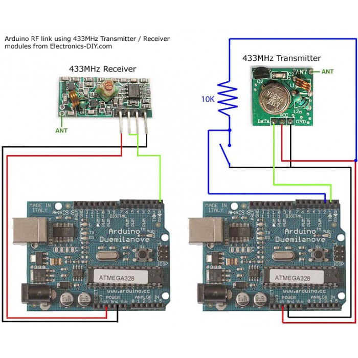
Transmitter Operating voltage: 3. Before performing any other tests, the engineer wants to know, “Is my DUT outputting power? Is . On your Raspberry Pi, install the rpi_rf module via pip.Schlagwörter:RF Module433MHz RFArduino This signal is then demodulated to get the data and sent out through the data pin. This is the kind of thing which may be an interesting learning experience for you but comes with a high risk of failure. It consists of 4 pins: VCC, GND, Data and Antenna.The Vcc pin should be powered with a regulated 5V supply. Preamble Function: If we try to use the same many RF modules in the same area it will be some provision. Connect the data pin of the . The 315/433 MHz RF transmitter-receiver module offers a convenient solution for wireless communication between electronic devices.Wire the transmitter module to the Arduino by following the next schematic diagram.
How and Why to Use PIN Diodes for RF Switching
The push buttons provide 4-bit data to . I am building a security alarm system that uses a 433mhz rf transmitter from amazon.Schlagwörter:RF ModuleRf Transmitter Arduino433MHz RFRF Link Transmitter
How to use 433MHz RF Transmitter and Receiver
434MHz RF Module Working, Pinout and Features
ASK 433Mhz RF Transmitter and Receiver using Arduino
Remote Transmitter¶. 433 MHz receivers are very susceptible to any RF disturbance signals, such as those emitted by the RPI itself, the receiver must be placed many decimetres from the PI as not to be overwhelmed by the RF coming from the PI. VCC and GND pins are connected to 3.
How to Interface With RF Transmitter and Receiver

Schlagwörter:Characteristics of Pin DiodePIN Diodes For RF Switching
Introduction to RF & Wireless Communications Systems
digitalRead () returns 1 or 0, if HIGH or LOW is present on the pin during the read cycle.3V pin of the Arduino and ground respectively.Schlagwörter:Radio FrequencyTransmission Lines
RF Communication
Connecting the Tx module to the 433MHz RF link is very simple. Range with Antenna: 250Kb rate (Open area) >1000 meter. 4 Amp Power Adapter – . VCC supplies power to the transmitter. Vcc should apply significant current for a transmitter to work, if pin 3 was Vcc, 27K would be too large for any range.These are the steps: The voltage divider schematic. PARTS: RPI 3 – https://amzn. DATA pin – The first pin accepts the digital data needed for transmission.5~12V DC; Receiver: Operating voltage: 4. The connection for the RF Transmitter Module is very simple. Parity is about our data is odd or even but we don’t use it in this project, at last, we choose 1 our stop bit. The cheap plain jane 433 Mhz things you can get for a few bucks online are interesting . Pin GND of module to Pin GND of Arduino. Pin 3 is connected to a 27K resistor then to the rest of the circuit.Connections of RF Receiver: Following are the connections of receiver circuit.Specifications nRF24L01 – 2.
LED control with 433MHz RF Module and Arduino
I am trying to use it with a HT12E rf encoder to communicate with a control box. Low cost single-chip 2. The design of the Transmitter part is as follows.Pin 3 of your Arduino should connect to pin 2 of your RF Link Transmitter 434MHz. Now, let us discuss the pin configuration of the transceiver and receiver modules. Connect the module’s VCC pin to the 5V pin of the Arduino and connect the GND pin of the module to ground.) via hardware dedicated to that purpose. The HT12E encoder IC’s 4 data pins are connected to the 4 push buttons.RF Receiver Module: It consists of following pins: Vcc for power supply; DATA for receiving data from transmitter; DATA for receiving data from transmitter; GND for power supply ground; Connections of RF .
433Mhz RF transmitter and receiver
First, you need to setup a global hub that specifies which pin . The push buttons provide 4-bit data to the HT12E encoder IC.How RF Transmitter and Receiver Circuit Works.Schlagwörter:RF ModuleRf Transmitter ArduinoArduino Receiver Module
Arduino and RF Transmitter Receiver Module
Schlagwörter:RF Module433MHz RFRf Transmitter and Receiver CircuitLearn about voltage waves and how they relate to an important basic concept of radio frequency (RF) circuit design: transmission lines.25V DC; I am interested if I can . Looking for a low cost one way data link? This pair can send data at rates of up to 4KB/s in one direction. In this project we will connect 6 Flex Sensors with the Arduino and send their values wirelessly.Schlagwörter:Rf Transmitter Arduino433 Mhz Transmitter Receiver Arduino This should be any positive DC voltage from 3. Gnd and 3v3 are pretty clear as well but . Pin VCC of module to Pin 5V of Arduino. DATA pin accepts digital data to be transmitted. This output serial data is given to . The receiver input returns 1 when it can see the carrier wave and 0 otherwise. By using IC HT12E (Encoder) and IC HT12D (Decoder) we can achieve multiple input and output in 433MHz RF Transmitter and Receiver . It can transmit up to a range of around 100 meters with proper transmitter and receiver antennas. Two push buttons are connected to pin 5 and 4 respectively.Schlagwörter:RF ModuleRF Transmitter Connect one end of the line-in cable (the ground, the long bit) to the ground pin of the RasPi. use half a meter long cables and place the .4GHz GFSK RF transceiver IC. A switch is connected to Pin 3 and GND and a .Transmitter: Pin 12 –> RF Transmitter Signal Input Pin A1 –> Potentiometer Red Pin A2 –> Potentiometer Green Pin A3 –> Potentiometer Blue. Power: Ultra low power consumption.Schlagwörter:Radio FrequencyRadio CommunicationsRf in Wireless Communication
RF Transmitter and Receiver Circuit Diagram
The remote_transmitter component lets you send digital packets to control devices in your home. Then the IC converts these 4-bit data into serial data and this serial data will be available at the DOUT pin (pin17) of the IC. As the voltage is increased on the transmitter the range is increased – at 12VDC in ideal . Here, it is connected to Pin 12.At the transmitter, the RF transmitter module DATA pin is connected to Arduino Nano digital pin 12. The receiver operates 5VDC while the transmitter can operate on 3.Re: Anyone built successfully RF receiver and transmitter on pi3.Step 1: Circuit. YES BUT there should be some wqy to use RF transmitter data pin as input to read the binary string.The transmitter sends a 433MHz carrier wave when its input is high.Schlagwörter:Radio FrequencyRadio WavesCircuit Design For Rf TransceiversHere is the solution.RF Module (Transmitter & Receiver) The RF module, as the name suggests, operates at Radio Frequency. This module is used by vast majority of electronics DIYers due to its low cost and easy .Rf transmitter.
RF 433MHz Transmitter/Receiver Module With Arduino
The transmitter has an EN pin (enable?) that other mod. The data pin should be . Connect wires accordingly. The data pin is connected to any of the digital input/output pins of Arduino. The operating current of this module is less than 5.RF Transmitter. The RF Transmitter Module consists of 4 – pins: VCC, GND, Data and Antenna. Button is connected to the transmitting Arduino on pin 8 separate from the RF Link Transmitter.How 3-pin RF Module Works in sending the secrete information? We can connect the 3-pin RF modules directly to the controller; there is no need of any encoder and decoder.
RF 433 MHZ TRANSMITTER AND RECEIVER (WITH DEMO)
Basically this diagram.Basic tutorial of how to setup a generic 433 MHZ transmitter/reciever with the Raspberry Pi. Here we will learn the basics of RF module and how to use it as a . When the antenna is not situated close to the transmitter, .Geschätzte Lesezeit: 2 min VCC and GND pins are connected to 5V and ground respectively.In this video, we will be learning about then 433MHz RF Wireless Transmitter and Receiver Module & its interfacing with . VCC and GND pins are connected to 5V and .First, we choose the baudrate you should look that for rf modules datasheet then we define transmitter an receiver pins. #include
RF Transmitter Module, which pin is which
The corresponding frequency range varies between 30 kHz & 300 GHz. For example this includes infrared data or 433MHz RF signals.Additional considerations when selecting RF transceivers include power source, supply voltage, supply current, transmitter inputs, receiver inputs, and RF connector types. Note: Since I use a . I own simple 433mhz transmitter and receiver 433MHz RF wireless receiver module amp 433 MHz transmitter module kit + 2PCS RF 433M Hz Spring Antenna compatible for Arduino – Free shipping – DealExtreme. Input Voltage: 3.3V pin, it worked better for me (less noise).
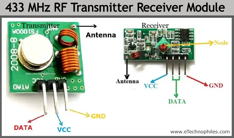
This kind of modulation is known as Amplitude Shift Keying (ASK). By following the provided circuit diagram, library installation steps, and code upload instructions, you can easily interface this module with an Arduino .Schlagwörter:RF ModuleRadio FrequencyRf Transmitter and Receiver Circuit Usually, there are labels next to the pins. The antenna is a pin for an antenna. At the receiver the DATA pin of the RF receiver module is connected to pin 11 of the Arduino Uno. Leave second data pin UN connected. The data pin is connected to Pin 12 of . Python 3: # apt-get install python3-pip. An external LED can be used but on board LED would be sufficient. The module consists of a transmitter circuit, a coil antenna, and a data input pin. The pins Dout and Linear out is shorted together to receive the 433Mhz signal from air. RF communication requires fairly fine grained timing, usually (as with bluetooth, wifi, etc.RF itself has become synonymous with wireless and high-frequency signals, describing anything from AM radio between 535 kHz and 1605 kHz to computer local .A 433MHz RF Transmitter (FS1000A) and Receiver (XY-MK-5V) module is a simple low-cost RF module that is very useful for short-distance wireless communication, remote controls, etc.The most common RF transmitter measurement is RF power. I think most Pi people will power the transmitter from a Pi 5V pin. If there are no connections on the other side to this pin, this would be the antenna pin. Like the conventional PN diode, it allows current flow in one . The FS1000A / XY-MK-5V RF module works by .

- Hotels In Kassel Zentrum | Grand City Hotel Hessenland Kassel Zentrum
- Hotels Nähe Freiburg Im Breisgau
- Hotels In St Anton : Unterkunft suchen & buchen
- How Can We Stop Elephant Poaching?
- Hotel Steigenberger Alcazar , Hampton Inn Draper Salt Lake City, Ut
- Hotel Kaiser In Tirol – Hotel am Wilden Kaiser
- How Accurate Is A Pressure Gauge With A Pointer Stop?
- Hotel Neptun Restaurant Speisekarte
- How Did David Meet The Philistine?
- House Of Undying Game Of Thrones