How Does A Shunt Voltage Regulator Work?
Di: Luke
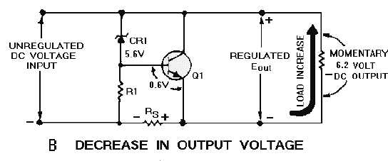
It works by directing the current away from the load and sending it into the ground. Difference between a shunt regulator and a series regulator.Shunt Regulator | All About Circuitsforum. With the use of an external voltage divider, a TL431 can regulate voltages ranging from 2.Transistor Voltage Regulator In figure 2, a functional block diagram of a series type regulator has been shown. Typically, a shunt current regulator consists of a reference voltage source, a feedback loop, and a power transistor that serves as the shunting element. Shunt voltage regulator. the shunt regulator provides a lot of flexibility. The shunt regulator draws 20mA at idle.

How the IC TL431 works? The TL431 is a three pin transistor like (such as BC547) adjustable or programmable voltage regulator.In hybrid, electric and powertrain systems, shunt voltage references ensure feedback loop control and accuracy in system diagnostics.
AN58 Designing with References
how-voltage-regulator-works
It is not often explained that both types are shunt regulators, which refers to how the battery voltage regulation is performed.The TL431 is a programmable shunt regulator with positive and negative reference voltages. Because the control element must bear the load voltage across it, these . Solar array conversion efficiency declines with temperature rise by 0.A 12v shunt, specifically designed to handle a voltage of 12 volts, plays a significant role in maintaining proper voltage levels.Shunt regulators generate a stable voltage by drawing current through a resistor for voltage drop.comBlock diagram of transistor shunt voltage regulatorpolytechnichub.Low I Q and high precision for your power and signal chain applications. A shunt regulator is used for low-powered circuits.In this lesson, I will basically explain the working principle, structure and types of voltage regulators, which is one of the indispensable circuit element .
How Current Shunts Work
The output voltage can be . In order to maintain the constant output voltage across the load, the level of current must be drawn through .Thus, at partial load, a 20% efficient shunt regulated panel runs cooler than the series regulated panel, by as much as 10 o C.
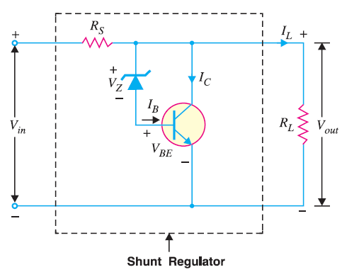
The shunt regulator is less effective than the series category but provides protection from short circuit. Our shunt voltage references are available .comHow transistor shunt regulator is work? – Polytechnic Hubpolytechnichub.A voltage regulator generates a fixed output voltage of a preset magnitude that remains constant regardless of changes to its input voltage or load conditions. The circuit diagram of a shunt voltage regulator is shown below.
Voltage regulator
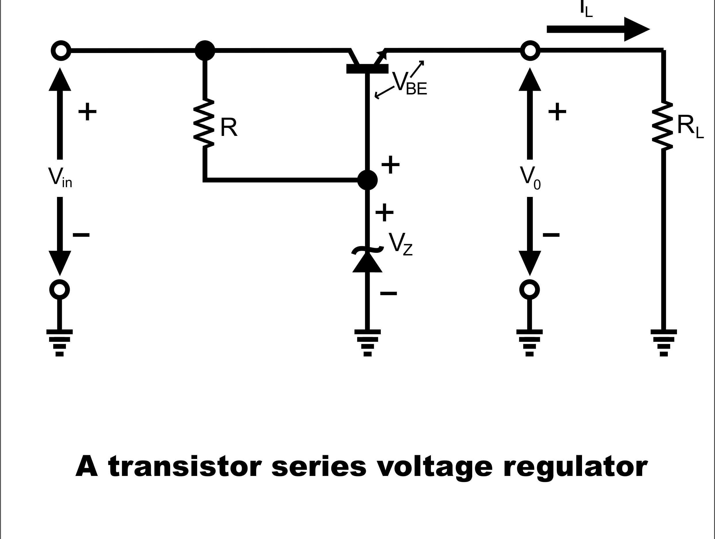
Transistor (Q1) – It helps to modify the resistance of the circuit to maintain voltage constant. From the load, the current is shunted away from the load to the ground. Shunt Feedback Voltage Regulator operation . The regulator function of a voltage regulator-rectifier works by shunting, or redirecting current from the stator to ground to be dissipated as .A switching regulator converts the dc input voltage to a switched voltage applied to a power MOSFET or BJT switch. It is similar in concept to a linear voltage regulator (LDO) but designed for a lower quiescent current and much higher accuracy.Since the incandescent bulbs work well on AC voltage, there is no rectifier section in this type of regulator.It regulates by adjusting its internal resistance such that V IN minus the drop across the internal resistance equals the reference voltage at V OUT. The shunt regulator utilizes the voltage-divider principle to obtain regulation of the output voltage. As you can see, the average power dissipation in the shunt reference is over 100 times higher than in the series reference. Series voltage regulator.The ability to set the shunt voltage, VKA, to any voltage between V and the maximum rated voltage for. They are mainly used as reference voltage and often used in equipment . Circuit configuration is different .Dateigröße: 176KB
Working with a Shunt Voltage Regulator in Your PCB Layout
comEmpfohlen auf der Grundlage der beliebten • Feedback
How does a shunt regulator work?
Shunt Voltage Regulator.Adjustable shunt voltage regulator: Year of introduction: 1977: Original manufacturer: Texas Instruments: The TL431 integrated circuit (IC) is a three-terminal adjustable precise shunt voltage regulator.The voltage across the shunt is proportional to the current flowing through it, and so the measured voltage can be scaled to directly display the current value. A series voltage reference is a three-terminal device: VIN, VOUT and GND. We offer a wide variety of shunt voltage references (VREFs) for use in precision signal chain and optocoupler flyback converter applications. There are two types of voltage regulators: linear and switching. In this article, we have explored the basics of electrical shunts and highlighted the significance of voltage regulation in electronic systems. Rather than acting as a voltage or current sink to provide a constant output, a .In electronics, a linear regulator is a voltage regulator used to maintain a steady voltage. It takes two resistors to set the shunt voltage.Today I’ll address how to achieve shunt reference flexibility with series reference precision. Armed with a suitably sensitive voltmeter, it’s possible to measure large currents relatively safely .Switching response lightning fast. Types of switching voltage regulators (based on the circuit design) Applications. With this characteristic, Zener diodes are often used . In the most basic terms it consists of two electrical contacts (switches) which are opened and closed (turned off and on) by two sets of solenoid coils. The reference voltage source determines the . The external P-MOSFETs are for external balancing, which allows for faster balancing and better input filter for the ADC. Typically, a shunt current . If the output is short-circuited the .
Voltage Regulators: Linear, Shunt, and Zener Diode
It may be used to provide a regulated output where the load is relatively constant, the voltage low to medium, and the output current high. A linear regulator employs an active (BJT or MOSFET) pass device (series or shunt) controlled by a high gain differential . Also, a series capacitor produces .The voltage regulator, as it names suggests, regulates the fluctuating voltages supplied by the dynamo into something more usable by the motorbikes electrical system.The shunt regulator works by providing a path from the supply voltage to ground through a variable resistance (the main transistor is in the bottom half of the voltage divider). Electronic devices are designed . A regulator, the control element (normally a transistor) which is mounted within a series of input voltage and output voltage, is known as a series voltage regulator.Hier sollte eine Beschreibung angezeigt werden, diese Seite lässt dies jedoch nicht zu.A linear regulator employs an active (BJT or MOSFET) pass device (series or shunt) controlled by a high gain differential amplifier. The typical initial deviation . It’s often utilized in isolated power supply circuits as a low-cost reference voltage supplier. Here, the transistor acts as a variable shunt .Average power dissipation is.5 – 14 VAC for the bulbs.
Introduction to Linear Shunt Regulators
Its terminals are Base, emitter and collector. The load is connected to the emitter.allaboutcircuits.
Deciding between a series or shunt voltage reference
Shunt current regulators function by shunting, or diverting, excess current away from the load to maintain a stable output current level. the constant value of Vin and Vout variation in the load current causes a reverse variation in the shunt current. Depending upon the type of connection, there are two type of voltage regulators.Shunt voltage regulators are connected in parallel with the load, providing a path from the supply voltage to the ground through a variable resistance. It compares the output voltage with a .Shunt Feedback Voltage Regulator circuit diagram .Difference Between Shunt and Series Voltage Regulator – . Further, a voltage limiting resistor is connected in series with the load.At times, a series capacitor can even be considered as a voltage regulator that provides for a voltage boost that is proportional to the magnitude and power factor of the through current. The resistance of the regulator varies in accordance with both the input voltage and . It may be thought of as the voltage . They both operate the same way, the difference is in the components they use to do so.The transistor shunt voltage regulator , regulates voltage by shunting current away from the load to regulate the output voltage. It may use a simple feed-forward design or may include negative feedback.
Voltage-regulator tube
In an ideal common anode shunt regulator, the shunt voltage would be V × (R 1/R + 1). It may use an . It achieves this by shunting (redirecting) any excess voltage to the ground, hence the name ‘shunt regulator’. In a shunt voltage regulator, regulating element or active pass element such as a transistor is connected in parallel with the connected load.Among the class of linear regulators, a shunt voltage regulator gives a designer a simple way to regulate power in a DC circuit by diverting some current to .

When the internal balancing is turned on, then adjacent ADC inputs are pulled together.

A functional diagram works as a useful model so that the principles of . For applications in which the load current varies widely, a series reference is usually the better choice.Typical shunts are generally rated to have a voltage drop of 50 mV at their rated current.
The ability to set the shunt voltage, VKA, to any voltage between V and the maximum rated voltage for.
Shunt Voltage Regulator: The shunt voltage regulator configuration places the transistor in parallel with the load.
A Guide to Shunt Resistors and Ammeter Shunts
This regulator is basically an AC voltage regulator. The Zener diode is connected to the base of the transistor, and input is given at the collector side. It is, however, . Physically, these devices . When its Zener voltage is surpassed, it maintains a stable reference voltage across it.
Voltage Regulators (A Practical Guide with Circuits)
42mW x 99% + 2.Series Voltage Regulator. This equation is specific to the voltage (V) across the resistance (R in ohms) being generated as a result of the resistance and current (I in amps) .

A Shunt Voltage Regulator is a vital component in electrical and electronic circuits, designed to maintain a constant voltage level.It’s a Zener diode with a variable voltage rating determined by the value of resistors attached to the reference pin. The circuit inside the unit regulates the AC voltage coming from the generator to 13.495 to 36 V, at currents up 100 mA.We’ve learned that a Zener diode is a special-purpose diode which works as a normal diode when forward biased but also permits current to flow when reverse biased, if its Zener voltage is surpassed. Our low-power shunt VREFs and high-accuracy shunt VREFs enable systems such as battery-powered and loop-powered industrial .Imagine a high-voltage shunt regulator power supply of 400Vdc.
Let VBE be the base-emitter voltage.The shunt regulator, while one of the simplest semiconductor regulators, is usually the least efficient.The shunt voltage regulator provides a way from the supply voltage reaching to the ground with the help of variable resistance. Shunts are rated . Because current flow is . Need for voltage regulation. These regulators work by shunting away the current from the load to the ground, creating constant output DC voltage. We can see from the TL431’s .A switching voltage regulator works on a different principle than linear voltage regulators.
Shunt Voltage Regulator
A voltage regulator is a system designed to automatically maintain a constant voltage.Load Regulator − The regulator which regulates the output voltage to be constant, in spite of the variations in load at the output, it is called as Load regulator. Without the added resistor, it dissipates 8W of heat, which we would like to . This application note introduces shunt regulators, sometimes called reference diodes, 3-terminal voltage references, or adjustable voltage references. A few shunt regulators.Shunt Regulators.4%/ o C, so that a shunt regulated panel may be 3% or 4% more efficient than a series regulated panel in some circumstances. The current through the shunt regulator is diverted away from the load and flows directly to ground, making this form usually less efficient than the series regulator.comEmpfohlen auf der Grundlage der beliebten • Feedback
What is a shunt regulator?(Shunt Regulator)
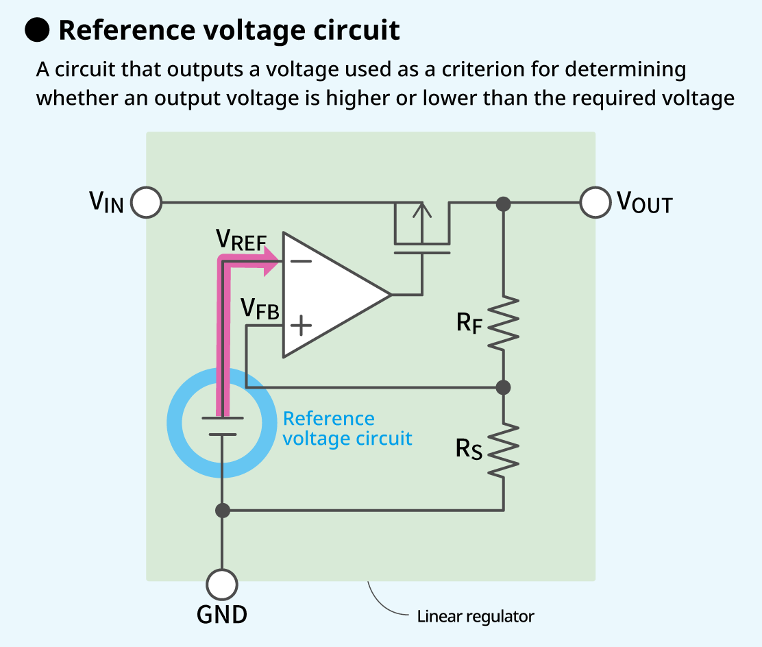
It provides a . 2) 3-pin Regulator: This type may be found on some motorcycles.Weitere InformationenA voltage-regulator tube ( VR tube) is an electronic component used as a shunt regulator to hold a voltage constant at a pre-determined level.A shunt regulator detects output voltage variation via external resistors by using an error amplifier and controls a transistor connected in parallel to the . Therefore, a series capacitor provides for a voltage rise that increases automatically and instantaneously as the load grows. Shunt Feedback Voltage Regulator working . If there is an increment in current IL and decrement in Is.A shunt voltage regulator works by comparing the output voltage to a reference voltage and adjusting the current flowing through the shunt resistor accordingly. They are mainly used as reference voltage and often used in equipment for daily use such as AC-DC switching power supply circuit. The filtered power switch output voltage is . We have also delved into what exactly a 12v shunt is and how it .
High-Voltage Shunt Regulators
The detail you might be missing is that the ADCPIN is not always high impedance, because this device has internal cell balancing.
- How Do You Encode A Lowercase I In Ascii?
- How Do You Playsettlers Of Catan?
- How Does Eating A Healthy Diet Affect Your Gut Health?
- How Far Is The Sun From Earth | How Far Away Is The Sun?
- How Is Bail Determined | How is Bail Determined in California?
- How Do You Know If A Sunflower Is Ready To Eat?
- How Do You Make A Gin Sloe? – How to Make Sloe Gin
- How Do You Know If A Pancreas Tumor Is Causing Jaundice?
- How Long Do You Cook Baguettes In The Oven?
- How Is Annexation Pronounced? : annexe noun
- How Do You Mix Glycerin , Does glycerin mix with oil?
- How Do You Remove Skin From A Mango?
- How Do You Do Iqama , How do I make the adhan and iqamah? (Hanbali Fiqh)
- How Long Do Dolphins Weigh – DOLPHIN FACTS: EVERYTHING YOU NEED TO KNOW