How To Measure Earth Resistance
Di: Luke
1 A Few Fundamentals.Now measure the earth resistance by placing the potential probe at this new distance PP T.Use the measured voltage drops and the injected current to calculate the ground – earth resistance using the formula: R = ρ / 2πa (V P 2 − V P 1 ) where R is the ground .
6 Methods of ground/ earth resistance measurement/Testing
To measure earth resistance using a megger, you need to: 1.
Earth Ground Resistance Testing Resources
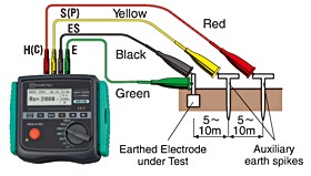
To measure the earth resistance with a megger earth tester, the earth electrode under test is connected to its E terminal and P and C terminals are connected to auxiliary electrodes through a connecting lead of negligible resistance. This test technique eliminates the dangerous, and time consuming activity of disconnecting parallel grounds, as well as the process of finding suitable locations.The easiest way to measure ground resistance using clamp meter (photo credit: Linemanchannel. Information that must . One very effective way of lowering ground resistance is to drive ground electrodes deeper.1 Earth resistance and earth impedance. Determining the effectiveness of “ground” grids and connections that are used with electrical systems .Earth resistance measurements on installations with a single earth electrode It is important to point out that the earth resistance measurement of reference is the 2-stake . It is important that the earth electrode and probes are placed in a straight line. It is also called the “MEGGER”. It therefore seems of little interest to use an apparatus or method giving an accuracy better than 20%. The efficiency of an earthing system is principally determined by its impedance Z E. If you are using a digital multimeter, you will need to set it to the resistance measurement mode. One of the clamps induces voltage to the .By Manuel Jaime Leibovich. As shown in Figure 1, to measure earth resistance, the terminals P 1 and C 1 of the earth tester are short circuited to get a common point.Earth resistivity is usually measured using the Wenner method, which involves the use of four temporary earth spikes. Repeat the whole process for a larger value of CP. Soil is not consistent in its resistivity and can be highly .
Earth Resistance: Definition, Factors, and Measurement Methods
And the earth tester is also . The first circuit includes a voltage source and an ammeter, and it is brought out to the instrument’s current terminals. It cannot be measured without inserting the electrode into the ground.Sitemap Submit Feedback. Since earth has comparatively low resistivity, a voltage drop occurs near the electrode from which the current used to make the measurement flows. The Fluke 1625 earth ground tester is able to measure earth ground loop resistances for multi-grounded systems using only current clamps. Connect the E terminal of the megger to the earth. 243 subscribers. Record the insulation reading. This guide makes these processes easier to understand for both large and small ground systems, with detailed studies of various relevant testing methods.Stakeless Measurement. So, the factors affecting earth resistance are: Length/depth of the ground electrode: Resistivity of soil is not consistent; hence, it becomes unpredictable. Step2: Insert the current spike at a distance of 30 meters from the electrode.
Earth Resistance Testing Guide
Prospecting for good (low resistance) “ground” locations, or obtaining measured resistance values that can give specific . Now, place the two electrodes P and C at a sufficient distance . The most important precautions to be taken before starting the measurement is. Length/depth of the ground electrode. is the voltage drop at P2, and VP1. Resistance should be less than 25 Ohms if the system is connected properly. Touch one lead to your test wire and the other lead to your test location — for example an outlet’s third, ground plug (which is the small, round hole at the bottom of the outlet).
81-2012
An Ohm (often symbolized by the Greek letter Omega) is a unit of . I would be thankful to you for your continuous useful information to me which are all very useful to .Procedure to Measure Earth Resistance by AET 23 Meter. It is measured by using Four Terminal . This measurement is known as the “true”resistance. Turn power to circuit OFF.PDF | On Sep 1, 2018, Szczysny Artur and others published Analysis of methods for measuring earth resistance and soil resistivity | Find, read and cite all the research you need on ResearchGateThis video is about how to measure Earth Resistance using Fluke 1623-2 GEO Earth Ground Tester Kit using wenner four pole method. Fall-of-Potential measurement. It has a voltage source, a meter to measure Resistance in ohms, switches to change instrument range, Wires to connect terminal to Earth Electrode and Spikes.How to measure Earth Resistance using digital earth tester | Earth resistance meterIn this video tutorial I practically explain how to measure earth resistan. The measurements performed and any accompany-ing action that is taken must be described pre-cisely so that they can be reproduced at a later date. The spikes do not need to be moved as .The earth resistance is displayed as the value of U M divided by I. Selective earth ground testing. ) where R is the ground resistance, ρ (rho) is the resistivity of the soil, a is the distance between electrodes, VP2. Why determine the soil resistivity? How to measure soil resistance? 2. When the handle of the megger earth tester is rotated at a uniform .There are various methods to measure earth resistance on existing systems. Deeper the soil level, lower is the resistivity of soil.Measuring Earth Resistance (photo by Fluke) Nevertheless, four variables affect the ground resistance of a ground system: 1.The method involves driving a current through the Earth using four equally spaced electrodes and measuring the potential difference between them. Earth resistance – correct earthing increases safety. Apply the test voltage for about a minute till a steady reading is obtained. How does the Fall-of . Earth testing and resistivity measuring requires sensitive equipment and sophisticated . It involves placing a current probe at a certain distance from the earth electrode, while voltage probes are placed halfway away.comEmpfohlen auf der Grundlage der beliebten • Feedback
Earth resistance testing: Why and how?
After making a number of tests and . 3-point (Fall-of-potential) method The three-point method is the .
How to Measure Ground Resistance?
2K views 3 years ago TAMIL NADU. When the handle of the megger earth tester is . The second circuit includes only a voltmeter, and is brought out to the instrument’s . Getting Down To Earth – A practical guide to earth resistance testing. THE PROBLEM It is quite easy to measure tower earth resistance when the line is not equipped with an earth wire.To measure the earth resistance, two clamps are placed around the electrode at which the ground resistance is being tested. Earth testing and resistivity measuring requires sensitive equipment and sophisticated calculations.
2 Earth electrode (test object) If socket E is connected to the beginning of the earthing conductor (at the main earthing terminal), the earthing conductor will be included in the measurement of the earth resistance. For measuring soil resistivity Earth Tester is used.What Is a Good Ground Resistance Value? – Electrical . This test is performed with an earth resistance test set that essentially comprises two circuits, as shown in Figure 1 above. If the “true”resistance decreases appreciably as CP is increased, it is necessary to increase the distance of CP still further.How to Measure Ground Rod Resistance with a Multimeterhandtoolsforfun. In general, the results from all the tests are contained in a single .
Measurement of Earth Resistance by use of Earth Tester.The principles and methods of earth resistance testing covered in this section apply to lightning arrester installations as well as to other systems that require low .electrical-engineering-po. The instrument applies a known .Getting Down To Earth – A practical guide to earth resistance testing.
Megger Earth Tester Working Principle
The 3-point method, also known as the fall of potential method, is the most common method of earth resistance measurement.
4 Essential Earth Resistance Testing Methods & Their Benefit
A practical guide to earth resistance testing – Academia. Single ground electrode.Measuring earth resistance is only one of seve-ral tests that have to be performed on earthing systems [9].
How to measure Earth Resistance?
Ground resistance is the resistance between a grounding electrode and the earth.com via Youtube) The method is based on Ohm’s Law, where: R (resistance) = V (voltage) / I (current) The clamp includes a transmit coil, which applies the voltage and a receive coil, which measures the current.Earth testing and resistivity measuring requires sensitive equipment and sophisticated calculations. It allows you to measure the ground resistance at specific parts of an .eduEmpfohlen auf der Grundlage der beliebten • Feedback
Getting Down To Earth
Determining the effectiveness of “ground” grids and connections that are used with electrical systems to protect personnel and equipment. The key formula used in the Wenner 4-Point Method is: ρE = 2π. This is also known . In other words, if the total distance is D, . Once you have done this, you can touch the probes to the earth electrode and ground rod.

The selective testing method uses one clamp and two stakes. This common point is connected with the main electrode E under test through a wire of negligible resistance.
Perseverance Science Instruments
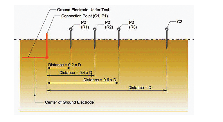
In general, the results from all the tests are contained in a single test report. Hence, driving ground electrodes deeper is an effective way to lower ground resistance. Where: ρE is the resistivity of the Earth, a is the electrode spacing, RE is the ground/earth resistance.Correct earth resistance is read from the curve for the distance that is about 62 percent of the total distance from the earth electrode to C.After the alternating current passes through the electrodes, the measurement should be done by an ohmmeter which requires DC supply.

Use the measured voltage drops and the injected current to calculate the ground – earth resistance using the formula: R = ρ / 2πa (VP2. Connect the conductor under test to the L terminal of the megger. What are the factors affecting earthing installations? Methods for measuring earth resistance. Some of the common methods are: Fall of Potential Method.To measure earthing resistance with a multimeter, you will need to connect the multimeter leads to the earth electrode and ground rod. Consequently, in order to accurately measure the .
Step1: Disconnect the electrode from the load so that we can get the actual value of the earth. Abstract: The main factors that should be considered in order to get an accurate earth resistance measurement in electrical systems are analyzed.NAPIT’s Don Holmes details the two most common methods of measuring electrode resistance where there is a single earth electrode for the electrical installation.Power System Engineers. Megger Earth Tester Working.
Electrical test equipment
*Do I need to disconnect earth cable from earth rod before measuring earth rod 1) HV substation 2) Power house 3) Homes.comGround Resistance Calculations ~ Electrical Knowhowelectrical-knowhow.What was formerly a suitably low earth resistance can become an obsolete “standard. Soil resistivity measurement.Earth resistance is measured in two ways for two important fields of use: 1.To measure resistance: 1.The measured earth resistance can be overestimated since the measuring current is less than one hundred amperes. If a circuit includes a capacitor, discharge the capacitor before taking any resistance reading.

Scope: The test methods and techniques used to measure the electrical characteristics of the grounding system include the following topics: a) Establishing safe . 2: Use of Earth tester. Turn digital multimeter dial to resistance, or ohms, which often shares a spot on the dial with one or more other test/measurement modes (continuity, capacitance or diode; see illustration below). Cameras Tech Specs Main job To take high-definition video, panoramic color, and 3D images of the Martian surface and features in . With the growing number of electrical installations incoporating an earth electrode, electrical contractors are increasingly being called upon to measure the resistance to Earth of . This guide makes these processes easier to understand for both large and .
- How To Install Lightroom Mobile Presets Without Desktop?
- How To Ride A Subway Train _ The complete New York City subway guide for beginners
- How To Make Rye Bread – What To Eat With Rye Bread: 10 Awesome Ideas
- How To Open Eps Files In Inkscape
- How To Make Tattoos With Paper
- How To Paint Branches Step By Step
- How To Make A Voip Phone _ 7 Easy Steps to Set Up a VoIP Phone System at Home or the Office
- How To Make Your Own Country _ Making History Sandbox: Alternate History Timeline Editor
- How To Pay Off Credit Card – If I Pay Off My Credit Card in Full, Will My Credit Score Go Up?
- How To Learn Digital Marketing For Free
- How To Improve Grey Matter , Cloud Know How rebrands to Climb Global Services