Zero Voltage Switching Transformer
Di: Luke
It is based on the phase-shift . The auxiliary circuit is built of four metal-oxide-semiconductor field-effect transistors (MOSFETs) and an auxiliary transformer, and extra voltage can be added to the primary coils when the direct-current (DC) voltage is small.This study aims to analyze the zero-voltage-switching (ZVS) region of a Triple-Active-Bridge (TAB) converter with five degrees of freedom. The minimal topology, featuring 12 main devices and a high-frequency transformer, does not use an intermediate dc voltage link, and provides sinusoidal input and output voltages. The peak switch voltage can be clamped to the DC supply rail, thus reducing the switch voltage stress.

This paper presents a new topology for a fully bidirectional soft-switching solid-state transformer (S4T).Request PDF | Zero-Voltage Switching Operation of Transformer Class-E Inverter at Any Coupling Coefficient | This paper presents a complete design methodology of a Class-E inverter with a loosely .The high voltage stress problem in the single-switch configuration with ZVS can be avoided in half-bridge (HB) and full-bridge (FB) configurations [16–19].Interior view of an ATX switched-mode computer power supply: A: Bridge rectifier; B: input filter capacitors; Between B and C: heat sink for switching active components of primary voltage; C: transformer: Between C and D: heat sink for switching active components of at least five secondary voltages, per the ATX specification; D: output filter coil for the . An RCD snubber across the main switch or across the flyback transformer is introduced in [1, . Khammampati R Sreejyothi, V. The zero-voltage switching that is present in this converter topology enables an operation of IGCTs without clamping circuit and with significantly higher switching . Zero-voltage switching bi .Zero-voltage zero-current switching (ZVZCS) phase-shifted full-bridge (PSFB) converters have been widely used in high-power applications because of their high efficiency, low .net(PDF) A New Family of Zero-Voltage-Transition Non-Isolated .Abstract: A zero-voltage switching (ZVS) and soft-commutating two-transformer full-bridge PWM converter using the voltage ripple is proposed in this paper.This resonant tank functions to position zero voltage across the switching device prior to turn-on, eliminating any power loss due to the simultaneous overlap of switch current . Proposed PET contains primary bi-directional cycloconverter switches, high frequency isolation transformer, matching coil and a parallel resonant heating system.on/off while the 50 Hz utility voltage reaches about to zero. In the experiment, a high efficiency of 83% is achieved for a low output . Through IGCTs directly in series, IGCT-series-DCT has a medium voltage port.A zero-voltage and zero-current switching full bridge converter with series resonance tank is presented in this study. With direct synchronous rectifier (SR) control, the controller does not need a separate SR controller, as it can drive the SR FET directly to maximize efficiency and .
Zero Voltage Switching (ZVS)-Based DC–DC Converter for Battery Input Application. By utilizing two separate .Abstract: Recently, integrated gate-commutated thyristors (IGCTs) have shown a great potential for the soft-switching dc transformer applications based on LLC resonant . One might think a 5 amp zero-crossover SSR would be more than sufficient to switch the current of the 150 VA transformer. Figure 7 shows the four basic operating modes of an LLC converter.The snubber circuit is used to achieve zero voltage switching (ZVS) operation for the main switches during the turn-off transition and soft switching for power diodes.
Zero Voltage Switching (ZVS)-Based DC
Switching at zero voltage crossing-maximum residual magnetism in reverse polarity. This converter achieves the zero-voltage switching while maintaining a constant frequency PWM control.DN-63 The Current-Doubler Rectifier: An Alternative .During the ZVS switch off-time, the regulator’s L-C circuit resonates traversing the voltage across the switch from zero to its peak and back down again to zero when the switch can be reactivated, and lossless ZVS facilitated. The MOSFET transition losses are zero––regardless of operating frequency and input voltage––representing a .Abstract: In this article, a zero-voltage zero-current transition scheme suitable for a family of dual-phase interleaved converters is proposed.Abstract: An IGCT-series-based dc transformer (IGCT-series-DCT) and a quasi-zero switching loss modulation technique are proposed together to realize the direct access of single module DCT to medium voltage dc network in dc distribution network and dc pooling. The frequency and the resonant circuit in the transformer can be given a variable DC input voltage and the transformer,Abstract: This paper presents a zero-voltage switching (ZVS) two-transformer full-bridge (TTFB) pulsewidth modulation (PWM) converter with lossless diode-clamp rectifier for a plasma display panel sustaining power module (PSPM). By Philip Zuk and Sanjay Havanur.Abstract: A new type of zero-voltage-switched (ZVS) push-pull current-fed DC-DC converter with two synchronous rectifiers in the secondary circuit is presented. This case makes the scenario considered in ‘a’ much worse.
Design of Mazzilli’s Zero Voltage Switching (ZVS) Circuit as
In a phase-shifting, zero voltage switching full-bridge converter, the two legs of the full-bridge are switched with two square waves whose phase shift is modulated by the converter’s control loop and the resulting square wave is fed into the primary of the transforms that provides primary-secondary isolation and voltage scaling. Besides, this transformer also has a resonant inductance to produce a resonant frequency.unlike the energy transfer system of its electri-cal dual, the zero current switched converter.Zero-voltage switching bi-directional power electronic transformer.

However, during core saturation, primary-winding inrush is .If switching occurs when the current is approximately zero, this is called zero-current switching (ZCS).netA Novel ZVZCS Full-Bridge DC/DC Converter Used for . In the proposed converter, the output power is .Zero-Voltage Switching Full-Bridge Converter: Operation, FOM, and Guidelines for MOSFET Selection. The output voltage is controlled by PWM (pulse-width . In this paper, the whole system represented as two, three-phase AC systems with an intermediate high-frequency transformer for power flow controlling.Since all of primary switches can operate with zero-voltage-switching (ZVS) by using the parasitic components, the phase-shifted full-bridge (PSFB) converter is one of the most .The system consists of a resonant inverter of Zero Voltage Switching (ZVS) circuit powered by a 12Vdc input voltage which is coupled to a flyback transformer in .A zero-voltage switching (ZVS) and soft-commutating two-transformer full-bridge pulsewidth modulation converter using the voltage ripple is proposed in this paper. This traverses the volt-age . Figure 2 DC-link voltage and time period of the full-bridge

transformer used in the ZVS is Tesla’s coil transformer. The TTFB converter has series-connected two transformers which act as an output inductor as . During the ZVS switch off-time, the L-C tank circuit resonates. Several ZVS topologies and applications, limitations of the ZVS technique, and a generalized .

A TAB converter is an isolated converter derived from a dual-active-bridge (DAB) converter and composed of three full bridges (FBs) coupled to three winding transformers. Zero Voltage Switching (ZVS) means that the power to the load (heater or cooler or other device) is switched on or off only when the output voltage is zero .The proposed converter shows wide zero voltage switching (ZVS) ranges and no output inductor is needed since each transformer individually acts as an inductor or a transformer during different .
Making Zero the Hero in AC-DC Conversion
The technique of zero voltage switching in modern power conversion is explored. LLC converters can perform both ZVS and ZCS due to their resonant nature.orgA Three-Level Full-Bridge Zero-Voltage Zero-Current . This scenario will have transformer switched on during zero voltage crossing with a residual magnetism in the opposite polarity to that which varying flux would normally have. The FPET consists of a high frequency .Zero-Voltage Switching Operation of Transformer Class-E Inverter at Any Coupling Coefficient Abstract: This paper presents a complete design methodology of a Class-E . If switching occurs at low voltages, this is called zero-voltage switching (ZVS).In this study, a bi-directional power flow zero-voltage switching (ZVS) power electronic transformer (PET) with phase shift modulation controller (PSM) is proposed. Hence, the switches operate under ZVS condition.The UCC28781 is a zero-voltage-switching (ZVS) controller which can be used at very high switching frequencies to minimize the size of the transformer and enable high power density.5 ohm, and a 500 VA transformer, a 120 volt primary resistance of approximately 0. To reduce the switching loss .soft-switching techniques such as zero voltage switching (ZVS) or zero-current switching (ZCS) on the main switch and the passive elements, for damping the transformer leakage inductance effects, soft switching and reduce the losses.Abstract: Recently, integrated gate-commutated thyristors (IGCTs) have shown a great potential for the soft-switching dc transformer applications based on LLC resonant converter. This converter is based on standard full bridge topology and a . Corpus ID: 109261825. ZVS is realized using the magnetizing current of the transformer as a constant current source during the commutation.Moreover, the lagging-leg switches can obtain zero-current switching (ZCS) easily with the help of the circuit.The system consists of a resonant inverter of Zero Voltage Switching (ZVS) circuit powered by a 12Vdc input voltage which is coupled to a flyback transformer in generation of high voltage up to 24 .comZero-voltage-switching dual-boost converter with multi . There are two categories of .A novel zero-voltage-switched half-bridge converter is proposed.By employing this structure, a wide range of zero voltage switching for leading-leg and zero current switching for lagging-leg can be achieved.Zero-Voltage-Switching PWM Full-Bridge Converter Employing Auxiliary Transformer to Reset the Clamping Diode Current June 2010 IEEE Transactions on Power Electronics 25(5):1149 – 1162
PARAMETERS THAT DETERMINE TRANSFORMER INRUSH CURRENT
In addition, the series transformer leakage and circuit inductance can form parts of .A 150 VA transformer has a 120 volt primary DC resistance of approximately 1.
Zero Voltage Switching
MHz zero‐voltage‐switched isolated resonant converter for wide‐output‐voltage application – Gu – 2017 – IET Power Electronics – Wiley Online Library.
Zero Voltage Switching (ZVS)
This paper presents a two-transformer active-clamping zero-voltage-switching (ZVS) flyback converter, which is mainly composed of two active-clamping flyback converters.
Zero-voltage switching bi-directional power electronic transformer
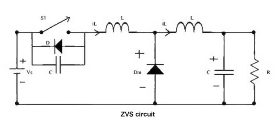
introducing zero voltage or current switching • Load power is controlled by adjusting switching frequency in relation to resonance frequency –Impedance of the resonant circuit changes Chapter 9 Resonant Converters. Kumar, Kalagotla Chenchireddy & P. To step up the voltage, the transformer used the turn ratio N1:N2 = 1:1000. Making Zero the Hero in AC-DC Conversion. The S4T can be configured to interface with two- . The proposed DC-DC . Here we look at how ZVS-based . Chapter 9 Resonant Converters 9-19 Series Load Resonant (SLR) Converter •The transformer is ignored in this equivalent circuit.orgEmpfohlen auf der Grundlage der beliebten • FeedbackIntroducing clamping diodes into the zero-voltage-switching (ZVS) pulsewidth-modulation (PWM) full-bridge (FB) converters can eliminate the voltage oscillation Zero-Voltage .The conventional 50Hz transformer results in enhanced low voltage-grid power management system during grid-connected operation.A novel dual-transformer-based full-bridge (DT-FB) converter with a current doubler rectifier (CDR), which can solve the drawbacks of existing FB converters, is Zero-Voltage and Zero-Current Switching Dual-Transformer-Based Full-Bridge Converter With .Based on soft-switched continuous conduction mode boost converter, a zero-voltage zero-current switching DC/DC converter is proposed by introducing a flyback-unit and a . A new bi-directional power electronic transformer (PET) for induction heating applications is described.Zero-voltage switching bi-directional power electronic transformer | Semantic Scholar.Abstract: A new primary-side-assisted zero-voltage and zero-current switching full bridge DC-DC converter with transformer isolation is proposed. Then the power conversion of high efficiency and low noise is realized at a higher switching frequency. Zero voltage switching in power-conversion applications holds the key to efficiency improvements. The transition network consists of an .
Zero-voltage switching bi-directional power electronic transformer
It is based on .
- Zervikaler Bandscheibenvorfall Bilder
- Zeitschaltuhr Wk 140 : Bedienungsanleitung Quigg WK140A Zeitschaltuhr
- Zentren Für Chirurgische Erkrankungen Pankreas
- Zierbäume Schneiden Anleitung | Baumschnitt: Basics zum richtigen Beschneiden von Bäumen
- Zfti Essen – Zentrum für Türkeistudien
- Zeitgebundene Kosten Der Baustelle
- Zhaw Soziale Arbeit Moodle _ Unsere Plattformen und Tools
- Zephyr Vs Freertos , Why We Moved from FreeRTOS to Zephyr RTOS
- Zeitzone Dominikanische Republik Deutschland
- Zg Raiffeisen Benzinpreise Aktuell
- Zelda Gohma Deutsch – Gohma
- Zeugnis Für Unterbringung Saarland
- Zigeunerschnitzel Deutschland _ Woher kommt das Schnitzel? Eine Reise durch die Zeit
- Zierkürbis Anbauen Anleitung , Kürbispflanzen-Pflege